

A lariat-based dilatation device for hysteroscopy: an in vitro study
Introduction
Hysteroscopy is a minimally invasive surgical procedure that requires the access to the uterine cavity for the treatment of intrauterine and endocervical lesions. This operation has been regarded as the golden standard for the therapeutic and diagnostic methods of many uterine diseases, such as dilation and curettage (D&C), sonohysterogram, hysterosalpingogram, and submucous fibroids (1,2). A preliminary cervical canal dilatation is required for standard resectoscopes to pass through a cavity to obtain an appropriate operating space, and plays a vital role in a successful operation procedure. Unfortunately, artificially ripening the cervix is still a clinical challenge, although many mechanical or pharmacological methods exist. A wide variety of cases, such as cervical stenosis, extreme uterine flexion or version, congenital anomalies, and scarring of the cervical anatomy by previous surgeries, can induce technical difficulties and complicated procedures during hysteroscopy (3). The failure ratio of the outpatient hysteroscopic procedures caused by the cervical stenosis and undue pain during the negotiation of the endocervical canal can be as high as 47 percent (4).
Obtaining enough operating space and clear vision in uterus are momentous in completing hysteroscopy. In order to solve these problems, carbon dioxide, normal saline and pharmaceuticals are generally used to dilate the uterus. Carbon dioxide or saline was filled into the intrauterine to form priming before the operation. However, carbon dioxide can induce hypercapnia, shoulder pain, nausea, vomiting and other complications and saline may cause trans urethral resection prostate (TURP) syndrome (5).
Compared with the methods mentioned above, the mechanical methods, such as the balloon-based devices and the osmotic dilator have the lower risk of hyper stimulation (6,7). A controllable balloon dilator can theoretically achieve the goal of gentle and effective cervical dilatation, and has achieved the higher success rate for cervical ripening (8). The single-balloon devices have been recommended as the best combination of safety and patient comfort among the mechanical operation devices and even the addition of extra-amniotic saline infusion to single-balloon devices may cause an uncomfortable traction and dripping sensation (9,10).
However, in addition to the discomfort, poor integrity and tensile function, low flexibility and narrow operating space are other adverse characteristics in the application of balloon-based devices. Previous researchers assessed the performance of a dilator made of several elastic wires (11). Operators can achieve four symmetrical windows with a total capture area of 40 mm2. This device can reduce the procedure time in endocavitary uterine surgery. However, sharp wires would lead to highly concentrated stresses on the tissue and therefore the risk of tissue damage. In the study, we designed a novel mechanical dilator with a diameter of 9 mm at its initial status to pass through narrow cervix after initial cervical dilation by cervical dilator. Its diameter could be expanded up to 60 mm at the working status to achieve a favorable operating space. The relationship between the tensions, the diameter of the dilator, and the visual/operating space were explored in vitro to ensure that this device could meet the requirement for hysteroscopy.
Methods
The experiment was divided into three parts: design of the mechanical construction, establishing the mathematical model, and in vitro experiment. All methods in this study were carried out in accordance with relevant guidelines and regulations. All experimental protocols in this study were approved by the ethics committee of Drum Tower Hospital affiliated to Medical School of Nanjing University.
Design of the mechanical construction
Construction of the dilator
The dilator was made of several identical units. The basic principle is shown in Figure 1A. In brief, the dilator unit is composed of many function blocks. There is a hole on the bottom of each block to allow a rope to pass through it, so that all function blocks are connected together. When the rope was relaxed, the dilator unit was flexible and longitudinally arranged in a line. After the dilator was inserted inside the cervix, the rope was tightened and every function block was compressed together for the purpose of forming an arc arrangement. The unit would convert into a rigid body to maintain this shape. To expose much space as possible in one operation, the width of the single component of the rigid body was set to 3.2 mm. To avoiding shading the pathological area, two expansions were required. When the first expansion and operation were completed, the rope was relaxed. The dilator was rotated about 30 degrees on the axis of the permanent seat. Then, the second expansion was performed, so that the hidden area would be exposed.

Construction of the operating system
The operating system was composed of two parts with a similar motion mechanism: the endoscope and the surgical instrument driving tube. The surgical instrument was located inside the driving tube. The hyperelastic wire (made of Nitinol) and driving tube was pre-bent into a certain shape (Figure 1B). The hyperelastic wire was inserted into the constraint tube as Herrell et al. (12). The angle and the location of the hyperelastic wire and the driving tube could be easily adjusted by changing their lengths outstretched the rigid tube or sleeve. The motion mechanism is demonstrated in Figure 1C. One end of the hyperelastic wire was attached on the lens mount and the other end was attached on the hand shank. The whole hyperelastic wire was in the rigid constraint tube and obligated into a linear shape as the sliding block was on the left. When the sliding block moved to the right, the hyperelastic wire was extended from the constraint tube and restored its pre-curved shape and the endoscope swung a certain angle. The device was achieved with the combination of the dilator and the operating system. Its general view is shown in Figure 1D.
Establishing the mathematical model
The structures of human organs are soft, so the interactions between the inner wall and the dilator and the interactions among various components are complex. In order to simplify the analysis, each function block was regarded as a rigid body in the analysis of distraction rod deformation. The shape of the dilator units will remain an arc-shape after any deformation and the range of force distribution in the arc will not be changed. The load applied on the dilator units by the organ inner wall is uniformly distributed and all the stress conditions of each dilator unit are the same. Supposing that the initial tension of each rope is T0, after the organ is distracted and the tension is T after the balloon is removed. The rope is considered as a linear spring. The deformation of the rope can be obtained according to material mechanics {Eq. [1]}.
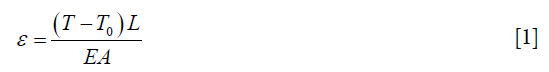
Where E was the elastic modulus of the rope, A is the cross sectional area of the rope, L was the length of the rope.
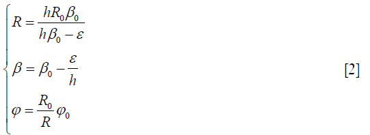
The force diagram of the dilator unit is shown in Figure 2A. R0 is the initial radius of the outer arc; s0 and l0 are respectively the initial lateral and medial lengths of the arc; β0 is the central angle of the initial arc; h is the height of function block; f is the uniformly distributed load of the inner wall on the dilator unit; φ0 is the central angle corresponding to the range of action; FAy and FBy are the forces between the base and the dilator unit.

The radius, lateral length, and medial length of the arc are changed to the R, s, and l after the dilator unit is deformed. The central angle of the initial arc is changed to β. The central angle corresponding to the action range is changed to φ. Each function block is a rigid body and s or h is not changed after the deformation. The inner arc is stretched to the length of l, where l=l0+ε. Eq. [2] can be obtained based on geometric relations.
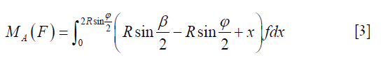
The torque on the pivot A by uniform load:
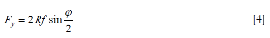
The component of uniform load in y-direction was:
According to the force and torque balance equations, we get:
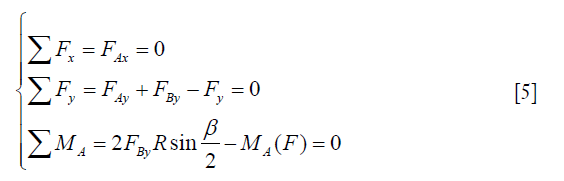
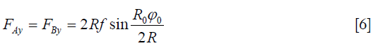
The reaction can be obtained after simplifying the Eq. [5]:
For the purpose of analyzing internal forces of the dilator unit, the left half of the dilator unit was taken into consideration. The force on the left half of the dilator unit is N. The tension of the rope is T. The force analysis is shown in Figure 2B. According to the force and torque balance equations, we get:
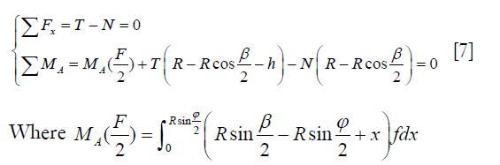
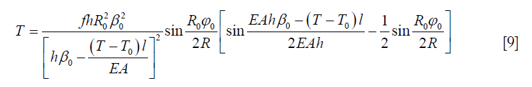
The tension of ropes can be obtained as:
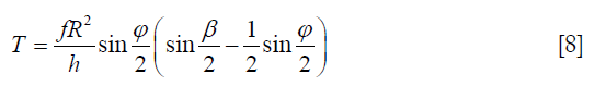
Eq. [9] can be obtained after substituting Eq. [2] into Eq. [8].
The relationship between the tension of organ and the pressure can be obtained:
The relationship between ft and f can be simplified, as shown in Figure 2C. The following equation can be obtained as:
Where n is the number of dilator unit.
According to the above equations, the tension T of the rope after loading can be obtained when the initial tension of the rope is T0. Then, the radius R can be obtained. The diameter of the expander can be obtained according to Figure 2D.
Where δ was the distance of symmetrical fulcrum and it was a constant value.
Establishing the motion coordinate system of the hyperelastic wire
In order to determine the observation range of the endoscope, a coordinate system was set for each rod (13). The origin of coordinate {0} was fixed in the top center of the operating rod (Figure 2E). z0 and the casing shared the same axis. The origin of coordinate {1} was fixed in the inflection point of the S-shaped hyperelastic wire. The axis of z1 and the tangent of arc A shared the same axis, and x1 pointed to the center of arc B. The origin of coordinate {2} was fixed at the end of the hyperelastic wire. The axis of z2 and the tangent of arc B were in the same direction and x2 pointed to the center of arc B. The origin of coordinate {3} was fixed at the center of the endoscope tip. The direction of each axis was the same to coordinate {2}.
The center of the endoscope tip had different laws of motion between the one case when the constraint tube caught only arc A and the case when the constraint tube caught both arc A and arc B. Therefore, two cases should be discussed separately. The movement distance of the slider is l; the initial length of arc A is l0; the initial length of arc B is s0.
The following conversion can be obtained according to the coordinate system, and relations when 0≤l≤l0.
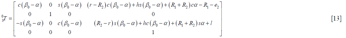
Where β0 was the initial central angle of arc B. R1 and R2 was the radius of arc A and arc B. The distance between the end of hyperelastic wire and the axis of the endoscope was r. The length of the endoscope was h.
The following equation described the relationship between α and l.

The following conversion can be obtained according to the coordinate system, and relations when l0<l≤l0 + s0.
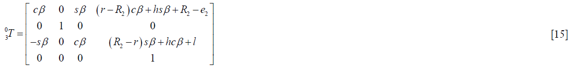
The following equation described the relationship between β and l.

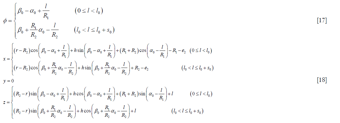
In summary, the swing angle and the end position of the endoscope had the following relationship.
In vitro experiment
In order to simulate the situation of real human uterus, a spherical structure consisting of three layers of airbags was employed in this study. The pressure required for the multilayer structure to expand to a diameter of 60 mm was 106 mmHg (about 14 KPa), which was similar to the continuous-flow pressure (110–175 mmHg) used in the clinical operation (14,15). The device was designed for hysteroscopy and tubal dredging, so a hysteroscopic micro polypectomy utilizing this mechanical dilator was carried out in the simulated uterus in the in vitro experiment. After the expansions, the dilator experienced a small deformation, which might affect the stress applied on the dilator. For the sake of facilitating the calculation, when the load was small, it was considered as a constant and calculated based on Eq. [10]. The main structural parameters of the dilator are shown in Table 1.

Full table
Results
Mechanical structures and working procedure
The working procedure is shown in Figure 3A. A balloon was settled at the center and wrapped with dilator units. After entering the uterus, the balloon was inflated and the dilator was expanded under the air pressure. After the dilator was expanded to the appropriate size, the rope was stretched to maintain the shape of the units and the balloon was deflated and extracted from the tunnel. In this manner, a clear field of vision was realized during the operation procedure. The removing process of the dilator is demonstrated in Figure 3B. The dilator could pass through the tunnel with a diameter of 10 mm easily. After the operation was completed, the ropes were relaxed to make the dilator become flexible. All the dilator units were movable and could restore their initial shape to produce the adaptive deformation, so that it could go through the narrow surgery channel, like the cervix.

The motion principle of the endoscope was similar to that of surgical instrument. In this experiment, the surgical instrument was biopsy forceps with a diameter of 1.75 mm. The biopsy forceps was placed into the pre-bent driving tube (with an inner diameter of 2.11 mm) and forced into a linear shape in the rigid sleeve. After extending from the sleeve, the driving tube could restore its original shape and the biopsy forceps could swing within a certain angle (Figure 3C). The biopsy forceps presented different angles according to the length of the driving tube extending from the rigid sleeve. The movement process of the lens mount is shown in Figure 3C. The lens mount could swing different angles according to the length of the hyperelastic wire extended from the constraint tube. In order to realize a wider observation and operation scope, the whole operating system with a diameter of 5.8 mm could be rotated by rotating the hand shank.
Validating the mathematical model
The minimum tension was calculated under different numbers of dilator units (Figure 4A). According to the calculation results, if the number of dilator units increased, the load on each dilator unit and the tension of each rope could be reduced. However, with the increase in the number of dilator units, the initial diameter of the dilator increased. In addition, too many dilator units covered a larger area of the inner wall of an organ and affected surgical operations. Under the premise of ensuring the strength of each rope, the number of dilator units could be reduced in order to decrease the diameter of the dilator. Based on the above analysis, according to the required tensile strength and minimum tension of the rope, the number of dilator units was selected to be six.

The minimum tensions at different heights of function blocks were calculated (Figure 4B). The minimum tension decreased when the height of function blocks increased. However, the initial diameter of the dilator increased with the increase in the height of function blocks. Therefore, under existing restriction conditions of the diameter, the maximum function block (1.9 mm) was selected.
The only variable parameter was the tension of the rope after the structural parameters of the dilator were fixed. Different forms of the expander could be obtained by controlling the tension of the rope. Therefore, it is important to explore the effect of the initial tension of the rope on the final form. As the tensile strength of the rope is limited, it is necessary to reduce the tension as much as possible under the proper expansion conditions.
In order to analyze the diameter of the dilator after the expansion under different tensions and loads, the theoretical calculation and experimental analysis were carried out in this study. The results are shown in Figure 4C. The curves of t1, t2 and t3 indicate the theoretical data of the expansion diameter under different initial tensions during the expansion process of one, two and three airbags. In contrast, the curves of e1, e2, and e3 indicate the experimental data of one, two and three airbags. Increasing the initial tension could increase the diameter of the expander after the expansion. When the initial tension reached a certain value, the diameter of the expander reached the maximum value and the variation trend tended to be gentle. As the load increased, the diameter decreased. This trend was different from the theoretical data because the block which was treated as a rigid body in the mathematical model was actually slightly deformed in the experiment.
The relationship between the swing angle of the end of lens mount and the displacement of the sliding block is demonstrated in Figure 4D. The swing angle was recorded when the slider was moved for every 2 mm. The swing process of the end could be divided into two phases. At phase 1, the experimental angle was less than its theoretical value because the large gap between the restraint sleeve and the hyperelastic wire led to a smaller swing angle of the end. The error could be offset in phase 2 due to the double-bending process during this period, so that the experimental results were consistent with the theoretical results.
Simulated hysteroscopic micropolypectomy
In the simulated surgery, a raised small polyp was stick on the inner wall of the multilayer structure. The simulated uterus was expanded in three continuous steps with the dilator (Figure 5A,B,C). After removing the balloon, the dilator acted like a cage to support the inner wall of the simulated organ and there was enough space in the cage, thus proving the functional feasibility of the expander. Then, the surgical instruments were thrust into the intracavity of the simulated uterus through the channel of the dilator. The raised polyp could be clearly observed and easily excised by the operator in such an adequate space. The process of the simulated surgery is shown in Figures 5D,E,F,G,H,I,J,K. The whole process was repeated for 5 times and the average operation time was 18.37±2.86 min.

Discussion
Although the safety and effectiveness of cervical ripening agents, including prostaglandin, vasopressin, and vaginal osmotic dilators, have been extensively explored to facilitate dilatation and decrease the risk of complications, the application of cervical ripening agents is still controversial (16-19). In the study, we designed a mechanical dilator based on the lariat structure to achieve the gentle expansion and enough operation space in hysteroscopy. The flexible multi-units could pass through the narrow cervix and the expansion diameter could be adjusted exactly by altering the air pressure in the balloon. Medical lubricants were applied on the surface of the dilator. The inner wall of the simulated uterus slid on the surface of the dilator, so that the tension of the inner wall tended to be uniform. More importantly, there is less liquid and zero interference in the operation space inside the dilator, thus decreasing the risk of infiltration caused by the usage of fluid or gas media and improving the reliability and safety.
For cervical priming before hysteroscopy, pharmaceuticals (like misoprostol) and natural osmotic dilators (laminaria) are commonly used and widely studied agents so far. The above-mentioned agents can ameliorate baseline cervical dilatation and prevent additional dilatation (20,21). However, these agents have common side-effects, such as abdominal pain, nausea, diarrhea, vaginal bleeding, increased body temperature, and long-term retention time. The balloon-based dilator, like Cook cervical ripening balloon and Foley catheter, can solve these problems to some degree. However, the most serious problem in balloon dilators is their large volume since they occupy the space in the cervix and uterus, especially in the cervix. Therefore, it is difficult for surgical instruments to extend and act in the uterus when balloon dilators are used. The previous study reported that additional cervical dilatation was required in almost all cases when the balloon dilators were used (22). Different from the balloon dilator, the novel lariat-based dilator structure had a channel with a diameter of 6 mm for an endoscope to pass through the intrauterine, so that the narrow space in cervix and uterus could be used sufficiently and the additional dilatation could be avoided. It was obvious that the experimental results were well consistent with the theoretical analysis in the dilatation simulation. Even though the friction between the rope and spring tubes exists, the fitting degree was improved with the increase in the tension of the inner wall in the simulated uterus.
The radial size of the dilator was so small before the expansion that the resistance to penetration when passing the cervical canal at its initial form was low. When the balloon was inflated, the whole uterus could be dilated synchronously so that the friction and the effective stress applied between the dilator units and the endometrium could be minimized. As the dilator units were fixed, the other surgical procedures could be completed by rotating the hand shank and pushing the sliding block.
Furthermore, the intrauterine space dilated by the lariat-based dilator was stable and the dilatation time could be easily controlled. The uterus was expanded by several dilator units and the contact area between each dilator unit and the inner wall of uterus was small, thus leading to a clearer vision field and easier manipulation. Besides, the contacting regions between the dilator units and the inner wall are continuous arcs, thus avoiding the damage to the endometrium. The shape and size of the dilator could be changed by adjusting the tension of the drive rope in order to adapt it to patients with different physiques and requirements during the operation.
The functional blocks were assumed as rigid bodies in the theoretical analysis. It was also assumed that no deformation occurred on the dilator units under different loads, indicating that the radius of the dilator was the same as the initially designed value. In realistic situation, they were deformed under the applied stress, thus resulting in the elastic deformation of the dilator units and compressing the dilator into an olive shape. The contact area between the dilator and the inner wall of the simulated uterus was arc and the stress concentration phenomenon was not observed during the simulated operation.
Some limitations existed in this study. Due to the friction between the rope and the functional blocks, the dilator units could not completely restore the linear state after relaxing the rope. The structure design and processing technology of functional blocks should be further optimized in order to improve the dilator. Additionally, due to the huge difference in the uterine anatomic structure between human and large laboratory animals, we did not carry out an in vivo experiment to validate the functionality and effectiveness of the dilator. We will make a dilator with a specific size for Bama mini pigs to complete the in vivo study in the future.
Conclusions
In this study, a mechanical dilator and operating system based on the lariat structure was designed to achieve gentle expansion and enough operation space in hysteroscopy. The dilator was made of several identical units and the identical units were composed of many function blocks. It could form a lantern shape to expand the uterus. The diameter of the dilator was 9 mm and it was small enough to pass through the natural cervix after initial cervical dilation by cervical dilator. There was less liquid and zero interference in the operation space inside the dilator, so that the risk of infiltration was reduced by avoiding the usage of fluid or gas media. The operating system was composed of an endoscope and the surgical instrument driving tubes, which had the similar movement mechanism. It was convenient to control the angle and location of the hyperelastic wire and tube by adjusting the lengths of hyperelastic wire and tube stretched outside of the rigid sleeve. The surgical instruments could complete some operations under the guidance of an endoscope. In the analysis, the number of identical units was determined to be six and the height of the function block was set to 1.9 mm. In the expansion simulation experiment, the diameters of the dilator after the expansion under different tensions and loads were obtained. The experimental results could guide the selection of the tension of the rope in future surgery. A simulated surgery was performed to verify the feasibility of the whole device. The dilator could support the inner wall of the simulated organ to act like a cage and there was enough space in the cage. Then, the operating system was thrust into the intracavity of the simulated uterus through the channel of the dilator to search for and excise the raised polyp. The experiment verified the feasibility of the designed dilator and operating system in principle. The study provides a new solution for the problems of organ expansion and operation in hysteroscopy.
Acknowledgments
Funding: This study was funded by the National Natural Science Foundation of China (51575100).
Footnote
Conflicts of Interest: The authors have no conflicts of interest to declare.
Ethical Statement: The authors are accountable for all aspects of the work in ensuring that questions related to the accuracy or integrity of any part of the work are appropriately investigated and resolved.
References
- Di Spiezio Sardo A, Mazzon I, Bramante S, et al. Hysteroscopic myomectomy: a comprehensive review of surgical techniques. Hum Reprod Update 2008;14:101-19. [Crossref] [PubMed]
- Christianson MS, Barker MA, Lindheim SR. Overcoming the challenging cervix: techniques to access the uterine cavity. J Low Genit Tract Dis 2008;12:24-31. [Crossref] [PubMed]
- Mei-Dan E, Walfisch A, Suarez-Easton S, et al. Comparison of two mechanical devices for cervical ripening: a prospective quasi-randomized trial. J Matern Fetal Neonatal Med 2012;25:723-7. [Crossref] [PubMed]
- Kremer C, Barik S, Duffy S. Flexible outpatient hysteroscopy without anaesthesia: a safe, successful and well tolerated procedure. Br J Obstet Gynaecol 1998;105:672-6. [Crossref] [PubMed]
- Nagele F, Bournas N, O'Connor H, et al. Comparison of carbon dioxide and normal saline for uterine distension in outpatient hysteroscopy. Fertility Sterility 1996;65:305-9. [Crossref] [PubMed]
- Jozwiak M, Bloemenkamp KW, Kelly AJ, et al. Mechanical methods for induction of labour. Cochrane Database Syst Rev 2012;3:CD001233. [PubMed]
- Yu D, Li TC, Xia E, et al. A prospective, randomized, controlled trial comparing vaginal misoprostol and osmotic dilator in achieving cervical ripening before operative hysteroscopy. Gynecological Surgery 2006;3:186-9. [Crossref]
- Pennell CE, Henderson JJ, O'Neill MJ, et al. Induction of labour in nulliparous women with an unfavourable cervix: a randomised controlled trial comparing double and single balloon catheters and PGE2 gel. BJOG 2009;116:1443-52. [Crossref] [PubMed]
- Ezimokhai M, Nwabineli JN. The use of Foley's catheter in ripening the unfavourable cervix prior to induction of labour. Br J Obstet Gynaecol 1980;87:281-6. [Crossref] [PubMed]
- Karjane N, Brock E, Walsh S. Induction of labor using a foley balloon, with and without extra-amniotic saline infusion. Obstet Gynecol 2006;107:234. [Crossref] [PubMed]
- Sudano MC, Vitale SG, Rapisarda AM, et al. The REP-b (removal of endometrial pathologies-basket) in-office hysteroscopy. Updates Surg 2016;68:407-12. [Crossref] [PubMed]
- Herrell SD, Webster R, Simaan N. Future robotic platforms in urologic surgery: recent developments. Curr Opin Urol 2014;24:118-26. [Crossref] [PubMed]
- Gosselin CM. Adaptive robotic mechanical systems: A design paradigm. Journal of Mechanical Design 2006;128:192-8. [Crossref]
- Wortman M, Daggett A, Ball C. Operative hysteroscopy in an office-based surgical setting: review of patient safety and satisfaction in 414 cases. J Minim Invasive Gynecol 2013;20:56-63. [Crossref] [PubMed]
- Kayatas S, Meseci E, O, Aydin T, et al. Experience of hysteroscopy indications and complications in 5,474 cases. Clin Exp Obstet Gynecol 2014;41:451. [PubMed]
- Lin YH, Hwang JL, Seow KM, et al. Laminaria Tent vs Misoprostol for Cervical Priming before Hysteroscopy: Randomized Study. J Minim Invasive Gynecol 2009;16:708-12. [Crossref] [PubMed]
- Karakus S, Akkar OB, Yildiz C, et al. Comparison of Effectiveness of Laminaria versus Vaginal Misoprostol for Cervical Preparation Before Operative Hysteroscopy in Women of Reproductive Age: A Prospective Randomized Trial. J Minim Invasive Gynecol 2016;23:46-52. [Crossref] [PubMed]
- Haya AF, Belal F, Hanan AK, et al. Preoperative ripening of the cervix before operative hysteroscopy. Cochrane Database Syst Rev 2015;4:CD005998. [PubMed]
- Hwang JY, Song SH. Optimal Dose of Vaginal Misoprostol for Cervical Ripening Before Hysteroscopy: A Randomized Double-Blind Study. J Minim Invasive Gynecol 2018;25:1031-4. [Crossref] [PubMed]
- Ghosh A, Chaudhuri P. Misoprostol for cervical ripening prior to gynecological transcervical;procedures. Arch Gynecol Obstet 2013;287:967-73. [Crossref] [PubMed]
- Liabsuetrakul T, Peeyananjarassri K. Mechanical dilatation of the cervix at non-labour caesarean section for reducing postoperative morbidity. Cochrane Database Syst Rev 2011.CD008019. [PubMed]
- Falcone F, Raimondo G, Stark M, et al. Balloon Catheter for Cervical Priming before Operative Hysteroscopy in Young Women: A Pilot Study. J Invest Surg 2018.1-6. [Crossref] [PubMed]

